
Inner Static Magnetosphere
Magnetic Confinement of Magnetosphere
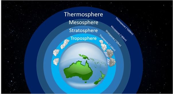
The image opposite is the typical 2D representation of the different layers of our atmosphere. It is well understood that the field lines are perpendicular to the surface of our planet at all points around the sphere. This means the direction of propagation must be perpendicular to the surface of the sphere in all directions. The spheroidal wave face loses energy as its surface area increases inversely to the rate of volume increasing, In the direction of propagation the energy in the wave obeys the conservation of energy, while perpendicular to the propagation the volume expands, thus the energy density decreases inversely under the Wave as distance from source increases (cyclotron wave loses energy inversely due to being perpendicular to the helical wave which conserves energy) .

Atmospheric Circulation
I have added to the original image courtesy of the ESA website linked on the image. The toroid shaped coil is position to show the source and trajectory of the Plasma inside the Planet. The 2D field lines on the right of the image are used to explain the split in flows between each cell, something that does not occur on Venus. The structural difference can be explained by using a spherical toroid where the polar vortices become part of the toroid, unlike Earths as shown below. Also added to the image is the Helical Vortex structures that form the High and Low pressure systems from the potential difference created in-between 2 adjacent cells. Like any Potential difference, current is generated and flows from high potential to low potential. It should be Firmly understood that in 3 dimensional space a difference in Potential energy can be opposite, but it can’t be negative potential as it remains the same height above the same reference point, thus it can only cancel out if it has an Equal and opposite component around a common axis. Which all spheres and helical 3D waves do.
The helical motion (wave) of all 8 quadrants of the spheroidal or toroidal Quadrupoles propagate outwards perpendicular to the surface thus creating a toroidal motion at 90 degrees to the surface around each confinement shell.
The creation of Potential differences between opposing toroidal rotating flows around the confinement shells induce current in the lower Atmosphere and from the current in the Hadley, Ferrel and Polar confinement cells is induced the High and Low pressure cells. The Jet Streams are also toroidal flows and can be consider “helically confined plasma current”.

Quadrupoles inside Dipoles
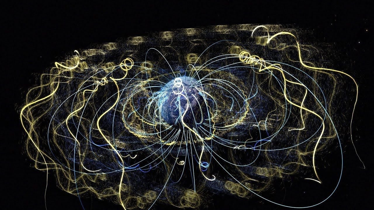
The Magnetic Model of Earths interior Toroidal dynamo was done by Los Alamos National Laboratory, as was the Plasma Squatter Man image. The 2 images show the same patterns of motion that generate the Quadrupole from the Poloidal perspective of the Magnetic field that is typical of any helical motion to rotating current around the Theta axis or Z-pinch axis. The helical rotation of Super-ionic Liquid Plasma around Earth’s central toroid produces the magnetic field of our Planet.
Top Left -The motion has been mapped in the Magnetic declination model. The inserted helical shape is the trajectory produced around a Quadrupole trap. The Helical motion around the quadrupole can be seen to roll 720* in 360*.
Top Right - a simple image using magnetic field vectors to show the direction of roll and the produced opposite declination of each quadrupole lobe.
Orange Toroids - centre tilted Toroid shows 2D Magnetic field vector and electric field vector, when combined they produce the 2 sets of 8 quadrupole lobes in 3 Dimensions only when the equal and opposite components of the toroid complete 360* of Roll (red arrow) in 360* or rotation (blue arrow). The 2 Polar vortices like flows that feed and extract Plasma from the Z-pinch also create the same combined vectors between magnetic and electric field lines. Due to difference between a Vortex and a Toroid, the motion that creates the Quadrupole changes to 720* of Roll in 360* of rotation.
Squatter Man Lobes - these 3 sets of Lobes are split across the Equator of each flow. When each of the 3 motions are in phase the alignment is synchronised to create a uniform Spheroidal shape to the Magnetic field.
Spheroidal Matryoshka Dolls
Matryoshka Spheroidal Dolls inside each other; a simple demonstration that can allow us to see 2 perspectives of each Spheroidal component of the overall Magnetic field structure. Colour coding the individual Spheroidal dolls identically with the opposite colour being painted on each opposite surface, eg; inside and out around the same hemisphere will be opposite.
The observers position relative to the distance from source, now has to consider that the declination of the field inward is the opposite to the declination of the same field outward.
This means that any object rotating in a magnetic field will observe a change every time it completes 180* of rotation, thus any rotating object must produce a rotating current inside its atomic structure. This happens as the “electron shells” rotate to the observed change, with electron shells around either end of the poloidal axis being colour coded red, blue, red, blue to form the Atomic Wave Functions Quadrupoles.